Tuning the Pietta Cap and Ball for Competition (Parts 1 and 2)
As seen in the June and July 2008 Cowboy Chronicle, reproduced here with bigger photos!
By Larsen E. Pettifogger, SASS # 32933L

Part 1: Diagnosing the Problem Areas
Cap and ball handguns are fun to shoot and if tuned properly can be very reliable. However, many pards buy a pair, go to a match, have problems, and then quickly become disillusioned with them and write them off as difficult and unreliable. We are going to go through the steps necessary to tune a Pietta C&B for competition. Like many things, a picture is worth a thousand words. So, I will try to illustrate as much as possible what needs to be done and try to suggest tools and ways of doing the job that a good home gun tinkerer can use to tune his/her Pietta.
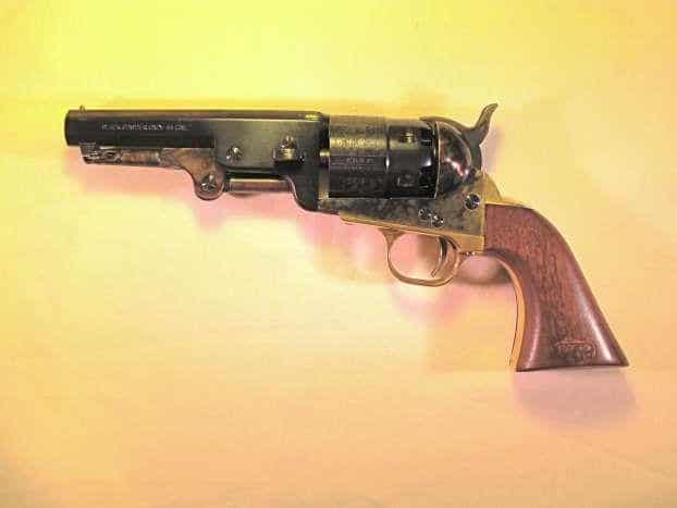
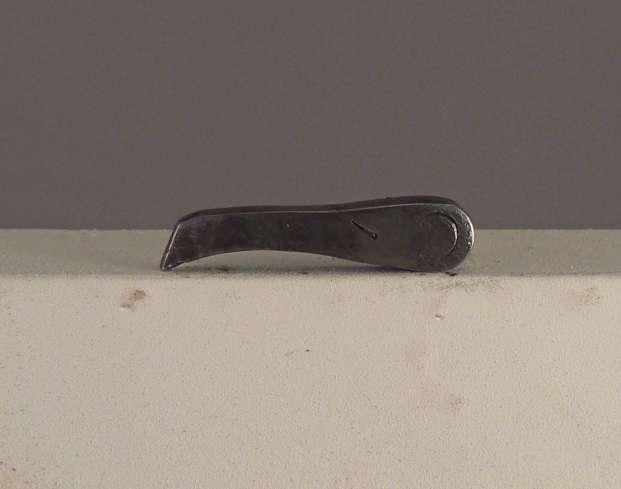
The revolver chosen for our tuning exercise is shown in Photo 1.

I picked up a pair of these from EMF at EOT 2007. They were under $200.00 each and it is amazing that these guns can be produced, shipped halfway around the world, and still sold for such an amazingly low price. They are described in the EMF catalog as the “1851 Navy Sheriff Model in .44 caliber with a 5 1/2” barrel.” As an historical note, there is no such thing as a .44 Navy. Whenever Colt advertised a revolver as being of “Navy” caliber, by definition it meant a .36. A revolver of “Army” caliber was a .44. Uberti tends to offer only guns that copy original Colts. Pietta mixes and matches parts to come up with a wide variety of interesting, but historically incorrect models. Our revolver is actually an 1860 Army frame and cylinder mated to a set of “Navy” grips with an octagon barrel bored out to .44. Although listed as a 5 1/2” barrel, it is actually closer to
4 3/4”. It will be a great shooter when we are done with it, and the shorter barrel will be quicker out of the holster than a 7 1/2” or 8” model.
Before we get started we need to discuss some of the tools needed for our tune-up. The first thing anyone needs when working on guns is a quality set of hollow ground screwdrivers. Hollow ground screwdrivers are machined so the sides of the tip that enter the screw slot are parallel. A regular screwdriver simply has tapered sides that taper all the way to the tip. Photo 2 shows a hollow ground and a standard screwdriver.

The parallel sides of a hollow ground screwdriver fit the screw slot tightly from the top to the bottom of the screw slot. A standard screwdriver fits in the slot like a wedge and only engages the top part of the screw slot. The quickest way to bugger a gun screw is to use the wrong type of screwdriver. We are going to be doing a lot of internal work and its hard to get light down inside the gun to see what is going on. Photo 3 shows an LED light that has a twistable neck and a magnet on the end of the base.

I picked this thing up in the checkout line at Walgreens Drug Store. It is an amazing little tool that costs less than $5.00 and can be found at a lot of drug and hardware stores. No matter what kind of light you have, your head or something always seems in the way and you can’t see down in small holes. This little gizmo solves that problem. Photo 4 shows a burr remover/metal scraper.

If your Pietta is like most, you will need one of these for the tune-up. (As an example, go to Enco.com and type in #380-0840. This should take you to a simple deburr/scraper tool.) You will also need a variety of needle files, preferably fine diamond needle fines (since some parts are hardened and difficult to file with a regular file), and some honing stones. Lastly, you will need a drill press and drill press vise.
The first step in any tune-up is to inspect the exterior of the gun and test the action to identify problem areas that will need fixing. The first thing, which isn’t exactly a “problem” but is an issue for many, is the grip shape. Photo 5 shows an original 1861 Navy (same grip as a 51 Navy) on top with our Pietta below.
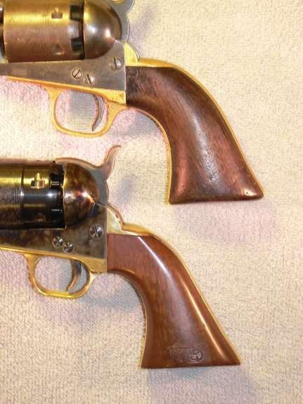
Colt spent a lot of time coming up with what many believe is the best grip ever put on a handgun. The 1851 Navy grip was so popular it was carried over into the Single Action Army. The original back strap has a compound curve (Photo 5, A) that starts at the top of the back strap and runs almost to the bottom of the grip frame and then curves slightly outward at the bottom (Photo 5, B). The Pietta grip is narrower front to back at “A” and the back strap is absolutely flat before turning out at “B”. The Pietta grip looks more like a trumpet bell. The wooden grip itself on the Colt is also thinner than the Pietta. For some, because of the angle of the back strap, the Pietta grip tends to cause the gun to point high. (Much like a Colt 1911 with a flat or arched mainspring housing.) We will modify the grip to be slightly more like an original Colt. The front strap is pretty close to an original and is fine as is.
Cock the action and look for anything that causes friction or binding. Raise and lower the hammer a few times and put SLIGHT pressure side-to-side on the hammer. On our
gun, the hammer was hitting on the left side of the frame and had already turned up a burr ever though the gun has never been fired. Photo 6.
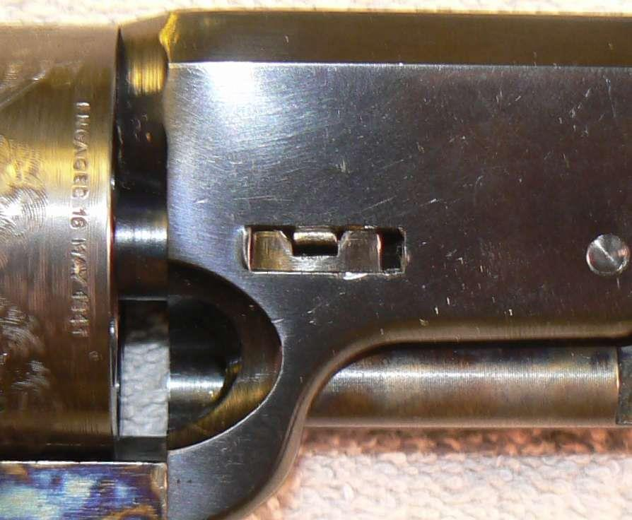
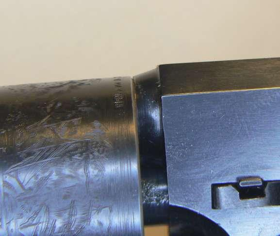
Something else that seems to be a problem on many new C&B’s is that the wedge is pounded in so tight it is difficult to remove. On our gun, the wedge didn’t stick out of the right side of the barrel and had been hammered in so hard it had puckered the metal. Photo 7.
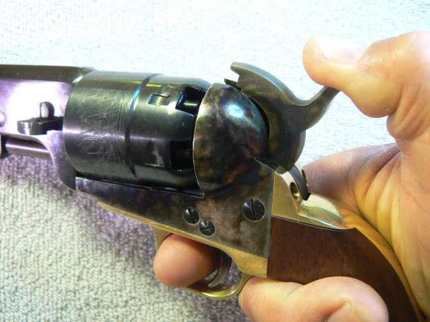
On a Single Action Army the frame is flat under the cylinder and you can visually check the timing of the bolt. On a Colt C&B the frame is curved, the cylinder is much closer to the frame, and you cannot see the bolt. About all you can do is slowly cock the hammer and listen for the bolt drop and then watch the cylinder to see how far it moves before the bolt locks up. The bolt drop will be the second “click” while cocking (make sure you keep your finger off the trigger or you won’t hear that first click), and you can look at the top locking slot in front of the hammer as a reference to see how fall the cylinder is turning after the bolt drops. It should only move about the width of the lead-in groove. Our gun is new, so timing was fairly good. Next, put some MODERATE back pressure on the cylinder. Photo 8.
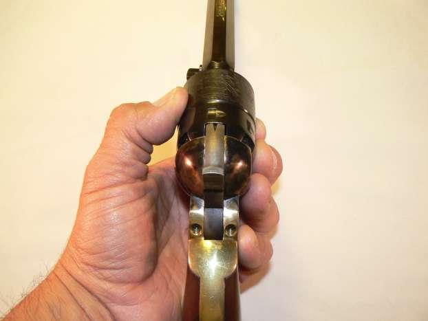
Do this for each chamber. On this gun, its mate, and several other Piettas I handled at EOT, most of them would unlock on at least one chamber. So, even though most Piettas (we are talking about the newer Colt style Piettas made in the last five years or so) feel like they are locked up “bank-vault” tight, they are not and that is the primary problem we will address in our tune-up.
Next, remove the barrel and cylinder. If the wedge is hammered in tight like our project gun, it will have to be hammered out with an aluminum or brass punch. Don’t use a steel punch or you will almost certainly mar the barrel. Proper wedge fitting is an issue we will address in our tune-up. If the barrel won’t come off, put the hammer on half cock, rotate the cylinder so one of the chamber walls is below the rammer and use the rammer to push the barrel off the frame. With a magnifying glass or magnifying visor, carefully inspect all of the cylinder notches. Our project gun has never been fired and has only been cycled a dozen or so times. Yet, all of the cylinder notches are already beginning to show wear. Photo 9 shows a notch with a little damage on the solid side (A) and a definite ridge already showing on the lead-in groove side (B).

What is happening is that rather than locking bank vault tight, our cylinder is simply getting a wedgie from the bolt. Fitting the bolt is the main part of our tune up. With the cylinder off, Photo 10 shows the frame is slightly miscast.

The left side of the frame is over 1/16” higher than the right side. This is cosmetic and won’t affect gun function.
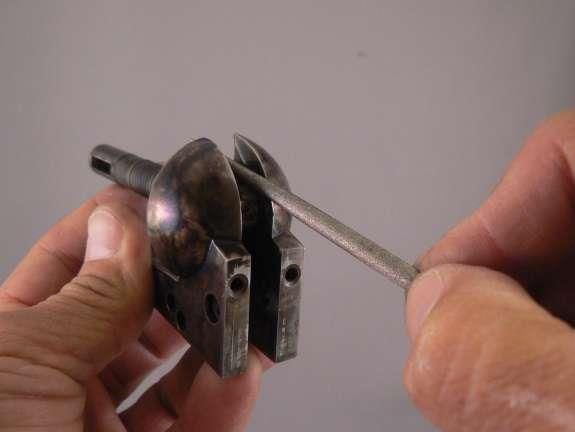
Next, we need to test the fit of the arbor. With the cylinder out of the gun, place the barrel on the arbor at a 90-degree angle to the frame and make sure the arbor is bottomed in the arbor hole. Photo 11.

(Make sure you stick the arbor in the arbor hole and not the bore!) Now, rotate the bottom of the barrel down until it contacts the frame. The barrel should set flush with the frame or just a few thousands up or down from the frame. Photo 12 shows our Pietta barrel mates perfectly with the frame.

Photo 13 shows an Uberti.

The Uberti arbor is far too short and the barrel sets well behind the front of the frame. There are exceptions to all rules, but in general Piettas have poorly fitted bolts and good arbor fit. Ubertis have properly fitted bolts and poor arbor fit. (We will tune an Uberti in a future article and fix a poorly fitted arbor.) Now we will begin final disassembly of our Pietta and look for obvious internal problems.
Remove the rear grip frame. On our project Pietta, as soon as the upper grip frame screws were removed the frame sprang down and back. Photo 14.
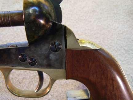
I could not get the screws restarted in the upper grip frame. The bottom screw also had quite a bit of resistance coming out. (Be particularly careful with any screw that is threaded into brass as they are easily stripped.) This will be corrected when we re-contour the back strap.
Before removing the trigger guard and internals, the bolt head should be carefully inspected. In order to get our gun to lock properly we are going to modify the bolt head. However, we need to be slightly cautious with the bolt. In order to lock up properly there are three things involved.
First, there is the width of the bolt window (the little rectangular opening that the bolt sticks up through) in the frame. Next there is the fit of the bolt in the bolt window and, finally, the fit of the bolt to the cylinder notches.
On our project gun, the bolt does not fit the cylinder correctly. Widening the bolt slots in the cylinder is beyond the capacity of most home gun tuners, so the only alternative is to narrow the bolt head. HOWEVER, we only want to narrow that part of the bolt sticking out above the bolt window in the frame. Photo 15.

If we narrow the entire head of the bolt it will fit the cylinder notches, but it will fit too loosely in the frame window and the cylinder will have excessive side-to-side play. Just to make sure what area needs to be narrowed, take a Sharpie and color the side of the bolt as shown in photo 16. (Only color the side shown, we will not take material from the other side.)

Now, remove the main spring, the trigger guard, the bolt/sear spring, the trigger, the bolt, and finally, the hammer and hand (some people refer to it as a pawl). Now that the bolt is out, be careful not to rub off the black color until we get around to fitting the bolt. Photo 17 shows the bolt and the area in black that is ABOVE the bolt window in the frame.

We do not want to remove material below the marked area. Photo 18 (A) shows the burr we identified when cycling the hammer.

With everything apart, it was also noticed that the arbor staking pin was sticking out and hitting the hammer. Photo 18 (B) and Photo 19.

Before ending this month’s installment, we’ll look at the relationship of the internal parts and explain how they operate so we will know what is needed when we refit the parts during our tune up. Photo 20 shows the hammer and it has a very nicely made and smooth hammer cam.

Photo 21 shows the bolt.

Although the Pietta bolt head is typically too wide, the bolt body is very nicely made and very smooth compared to many other Colt clones. It has a very nice bevel on the end of the bolt leg that rides on the hammer cam. See above Photo 21 (B).
Many bolts are fitted with virtually no bevel or a very roughly ground one. Essentially, how the bolt operates is that at rest, the bottom curve on the bolt is sitting just above the top of the hammer cam. See above Photos 20 and 21 (A).
As the hammer is cocked, the top of the hammer cam pushes up on the bottom of the bolt and the front of the bolt tips down (like a teeter-totter) and unlocks the cylinder. As the hammer travels further to the rear, the bolt leg slips off the top of the hammer cam and the bolt rises to lock the cylinder.
The bottom of the hammer cam is shaped like a hatchet head pointing down. The bolt bevel is shaped like a hatchet head pointing up. See above Photos 20 and 21 (B). When the trigger is pulled the hammer drops down and the two hatchet heads pass each other. Since the hammer is stationary vis-à-vis side-to-side movement and is stronger than the leg on the bolt, the hammer cam pushes the leg of the bolt inward. Photo 22.

When the hammer is all the way down, the leg of the bolt snaps back over the top of the hammer cam and the process begins again for the next shot. (In Photo 22, the bent leg is riding over the hammer cam and will snap back to the left when it reaches the top of the cam.)
That’s why we need the little light described in the beginning of this article. We are going to modify the bolt and need to be able to see that it is working properly.
Finally, Photo 23 shows the relationship of the hammer and trigger.
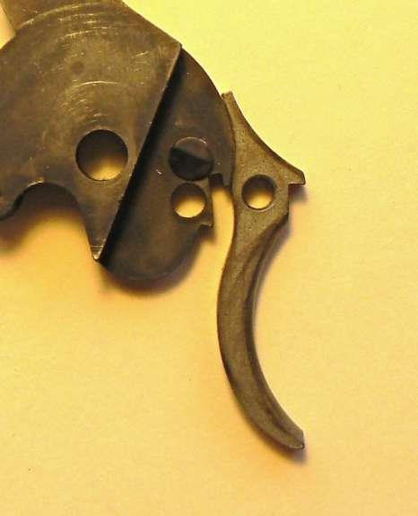
The top of the trigger above the trigger screw hole slides along the front of the hammer until the trigger tip drops into the half cock or full cock notches. On a lot of guns, the back of the trigger or front of the hammer is very roughly ground and you can feel grittiness while cocking the hammer as the trigger drags over the front of the hammer. On our project gun, the front of the hammer and back of the trigger is smooth and need little, if any, polishing.
Next, we will correct all of the problems we have identified and reassemble and test our Pietta. Make sure you keep this issue of the Chronicle as we may need to refer to some of the photos when correcting problems or reassembling our gun.
Part 2: Fixing the Problem Areas
Tuning the Pietta Cap & Ball for Competition
Part 2. Fixing the Problem Areas
By
Larsen E. Pettifogger
SASS # 32933L
In our last session we diagnosed problems and disassembled our Pietta .44 Sheriff’s Model. This month, we will fix the problems we identified and reassemble and test our revolver. While our revolver is apart, if you see a burr, remove it. If you see any surfaces with bright marks, polish them. We want every surface that produces friction as the revolver is cycled to be as smooth as possible.
Our on project revolver we’ll start with the frame and hammer. Smooth and polish the problem areas we identified in the hammer channel in part one. Photo 1.

LIGHTLY break any surfaces on the frame that have razor sharp edges. We don’t want to remove any appreciable amount metal or change the frame contours, we just want to lightly dull the sharp edges. Photo 2.
A small diamond file is used to very LIGHTLY brush over the frame’s sharp edges and dull them. Install the hammer and make sure it moves freely in the hammer channel. (Don’t tighten the hammer screw to tightly. If the hammer is a close fit, it is possible to tighten the hammer screw enough that it will bind or put drag on the hammer.)
Again, like we did in part one, put very light side-to-side pressure on the hammer as it is moved up and down in the frame. Even after smoothing the hammer channel and breaking the channels sharp edges, on our project revolver the sides of the hammer had a little bump on the down stroke. This was caused by two sharp corners on either side of the hammer. These corners were dulled with a stone. Photo 3.
It isn’t necessary (or possible on some guns) to completely remove all side-to-side hammer contact. What we want is a smooth transition in the event the hammer happens to rub on the frame while shooting. Once the hammer moves smoothly in the frame, we will move on to the most critical part of our tune-up–fitting the cylinder bolt to the cylinder.
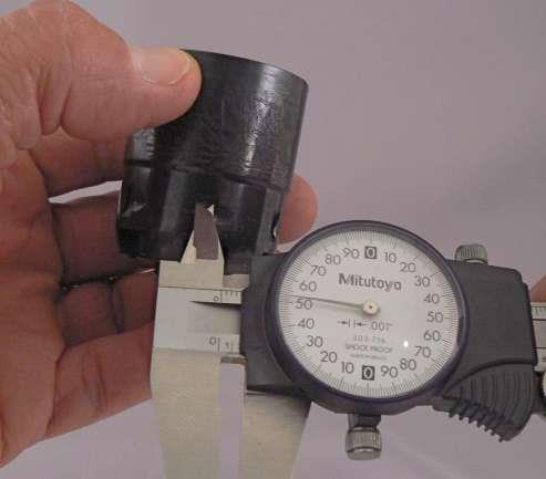
If you reload, you probably already have a dial caliper. If not, they can be obtained from a variety of sources. If you do any gun work or reloading, it will be invaluable. Measure the cylinder notches on both ends and in the middle of each bolt notch. Remember, the bolt notches are offset so make sure the calipers are square to the notch. On our
project revolver all the notches measured around .153” on the ends and .145” in the middle. Photos 4 and 5.

As we had previously diagnosed, the bolt appeared too wide and was peening the bolt notches. Our bolt measures .157”. Photo 6.

So, our original diagnosis was correct, the bolt is clearly wider than the bolt notches. Just to double check your measurements, try to insert the bolt into the bolt notches. Remember, the notches are offset so the sides of the bolt must be kept parallel with the sides of the bolt notches. Photo 7.

Check all of your notches and try the bolt in each notch. IF your cylinder bolt measurements are all greater than the width of the bolt and the bolt it goes into all the notches, then you can sit back and relax and skip the next operation.
On our project revolver, the bolt would not go into any of the cylinder notches, especially since all of the notches were already showing signs of peening. Photo 8 shows a cylinder that was already ruined from peening and also shows the results of an attempt to square the notches with a Dremel.

The cylinders on our black powder revolver are soft. Thus, we can re-square the notches with a de-burring tool like that pictured in Part 1.
Put the point of the tool in the bottom of the notch (on the same side as the burr) and make sure the side of the blade forms a 90 degree angle with the bottom of the notch and drag the blade along the notch. This may need to be done a couple of times, but the tool will cut the burr away and leave a nice clean square notch cut.
Do this for all notches that have damage.
On our project revolver, this was all six notches. Re-measure all of the notches; they should now be fairly uniform. If the middle measurement on any notch is still markedly smaller than the ends, you may need to remove a little more material with the de-burring tool.
Now determine the smallest notch. On our project revolver, all the notches were between .152” and .154”. In Part 1 we marked the bolt with a black Sharpie. Keeping the cut as square as possible, stone this area down until it is .002” or .003” thinner than your smallest notch. On our project revolver the bolt was cut from .157” to .150”. Photo 9.

Put the hammer in the frame and then the bolt and bolt/trigger spring. (You don’t need to install the trigger.) Put on the back strap so you know the maximum the hammer can be cocked when the revolver is fully assembled. (On our project revolver it was noted in Part 1 that the back strap was sprung.
When it was attached to the frame for this step, it was also determined that the screws were bottoming in the frame and the back strap couldn’t be fully tightened. This wasn’t noticeable when the gun was assembled because of the tension put on the screws by the sprung back strap. If you screws do this, shorten them so the back strap can be fully tightened.)
Push the hammer back and forth in the frame and watch the bolt retract and then pop back up. Also, feel how smooth the hammer feels when the bolt leg passes over the hammer cam when the hammer is moved forward to its seated position. You can shine some light in the frame with the little light discussed in Part 1 and watch the action of the cam and bolt leg. When we originally looked at our hammer and bolt in Part 1, it was observed that the hammer appeared to have a nicely formed and smooth cam and the bolt had a nice bevel. However, that nice flat spot on the cam caused more drag than anticipated. By looking at the cam and bolt leg while they were moving over each other it could also be seen that the flat spot was dragging on the bolt below the bevel cut into the end of the bolt leg causing the bolt leg to flex inward more than needed. The top of the cam was polished with a fine stone. The bevel on the bolt leg was blended a little further down the bolt leg to make its transition over the cam a little smoother and then polished. Photo 10 “A”.

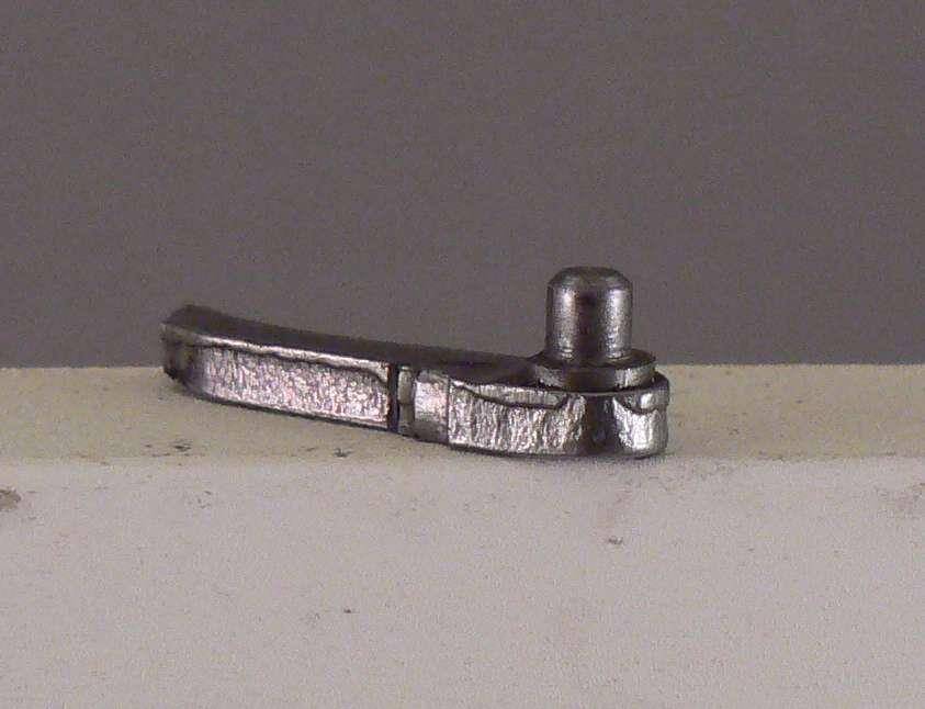
Now that the hammer and bolt are working properly, we can move on to the hand. One of the major reliability areas in a Pietta revolver is the hand and hand spring. The hand is soft and the hand spring breaks frequently. Hold the hand in one hand and pull the spring straight down. Photo 11.

See how easy that broke off! Photo 12.
Now that it’s broken, we’ll fix it permanently. For this step, do not try to remove the broken-off stub. We want it in the slot. With the hand spring gone, you can see how rough the back of the hand is. Photo 13.
Smooth it so that you have nice curves and a polished surface all around the back of the hand. Photo 14.
When smoothing the back of the hand the little piece of the hand left in the slot now forms a nice little plug so there is no gap in the back of the hand. You want to smooth and polish over the little stub because depending on where we drill the hole for the next step, the plunger on our modified hand may ride over the stub. With a stone, smooth all the little burrs that are typically found on the tip of the hand. Do not change the contours, merely smooth out the burrs. After the tip is smoothed up, we want to try and harden it a little. Hold the hand in a pair of pliers and heat the tip with a propane torch until it is red hot and then immediately submerge it in a bucket of water. Photo 15.
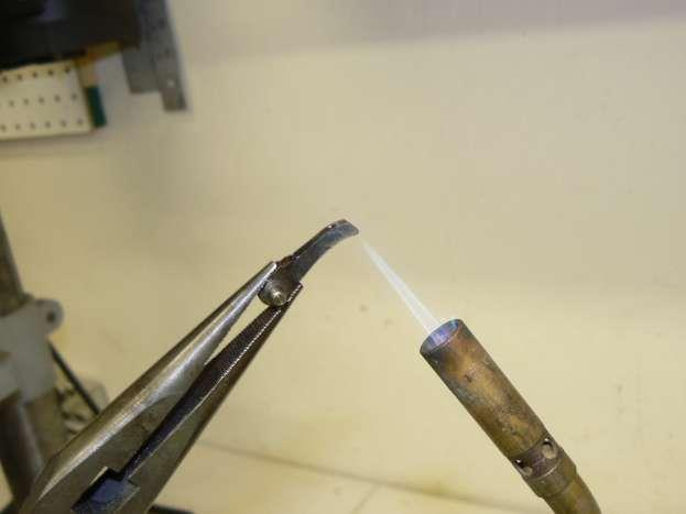
This isn’t the best method for hardening steel, but it will help a little with the dead soft metal in our hand.
Next, we are going to drill a hole in the frame and install a Ruger style plunger and coil spring. Ideally, the plunger should ride in the middle of the back of the hand. To determine where to drill the hole, measure the width of the hand. Our hand is just shy of .120”. Photo 16.

The middle of the hand would be .060”. (There is a lot of slop in the hand slot, so we can round the numbers a little to make locating the hole we are going to drill easier.) However, our project revolver’s hand has a boss on the bottom to space the hand out from the hammer. The boss is shown in Photo 13 at “A”. (Some hands have this boss, some don’t. You need to take a good look at the one in your revolver. If there is no boss, then the final measurement is simply half the hand width.) The boss on our project revolver’s hand is roughly .040”. Thus, half our hand width, .060”, plus the width of the boss, .040”, is .100”. The next thing we have to do is figure out how big a hole to drill and where to put it.
One nice thing about splitting this article into two parts is that it gave me a chance to solve a problem and make the next step a little easier.
On gun one (remember, we actually started with a pair of revolvers) I installed a standard Ruger plunger and spring as used in all of the Ruger single action revolvers. On some Piettas the stock Ruger spring and plunger work perfectly. On others, the plunger is too short and would fall into the hand slot or hang up on the edge of the hand slot.
The original article text and photos described how to test for this problem and showed how to correct it by making a longer plunger out of a piece of drill rod. I had two more new Piettas on the shelf and both of these also had a wider hand channel than some of the older models. I decided to see if a different set of parts would work better. After ordering and trying different part combinations, the following parts should drop in and function fine with no modifications.
Ruger Pawl Spring Plunger KE51 (Brownells part no. 780-001-231) and Ruger Cylinder Latch Spring KH05000 (Brownells part no. 780-000-464). These are actually out of a Ruger double action, but will work fine in our project revolver. The original Ruger single action plunger and spring is shown on the top of Photo 17 and our new combination double action plunger and spring is shown below it.
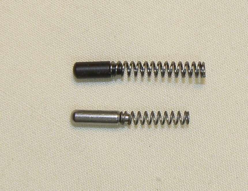
The new plunger is smaller in diameter, which will work fine in our application as it will give more clearance when we drill our hand spring hole.
Drilling the hole must be done with a drill press or milling machine. The frame must be held so the back of the frame is parallel to the drill table. Do not attempt to drill the hole by hand! How exactly the hole gets drilled will depend on the tools available. The best
method is to drill the hole in a milling machine using a starter drill to start a pilot hole and then drill the remainder of the hole. The hole can also be drilled on a drill press with a good drill press vise.
We want to measure in .100” from the left edge of the hammer channel. If using a drill press take a Sharpie and blacken the back of the frame. Measure in .100” and scribe a line. The other dimension is basically to move down from the top of the machined surface on the fame so that when the hole is drilled it is covered by the back strap. This measurement is not as critical as the .100” measurement in from the side of the hammer channel. Scribe another line and then with a very fine punch, make a punch mark at the intersection of the two lines. See, Photos 18 and 19.


Do not attempt to start the hole on a drill press without a punch mark to guide the drill tip. If you do, the drill bit will skate on the hardened frame metal and you might wind up with a hole, but it will almost certainly be in the wrong place. The hole size is a number 42 drill which is .0935”.
Number drills can be obtained at most hardware stores and hobby shops. Complete sets of number drills can also be obtained at Harbor Freight. After the hole is drilled, make sure any burrs on the inside of the hand channel are removed. This can be done by running a small file up into the hand channel and over the hole a few times.
Put the plunger in the hole and make sure it moves freely in the hole and into the hand channel. If the plunger is dragging, take the number 42 drill and rotate it back and forth between your fingertips while moving it in and out of the hole. This will help remove any tiny burrs. Once the plunger moves freely in the hole, we are ready to move on to the next step.
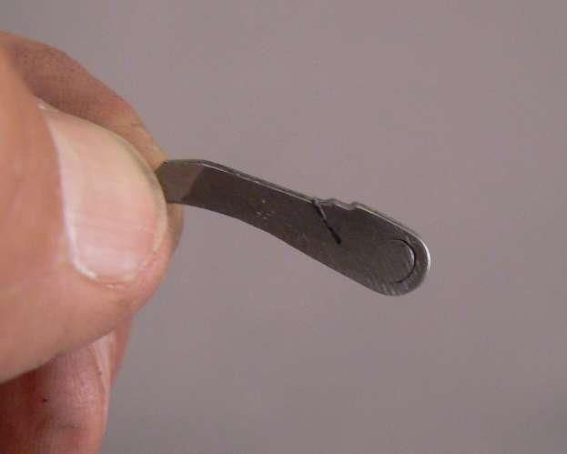
On our project revolver, the wedge was hammered into the barrel so tightly that it had raised a bump on the side of the barrel. The wedge should be able to be inserted and removed from the barrel with finger pressure or a light tap from a screwdriver handle or some other non-metallic object. Run the wedge back and forth on a fine tooth file until one side is flat. Photo 20.

Then put the wedge on a stone and polish that side until it is smooth. Photo 21.

Repeat the process on the second side of the wedge, testing frequently, until the tip of the wedge spring just sticks out of the barrel with thumb pressure on the wedge. Photo 22.

When the gun is shot, the wedge will loosen a little more and the wedge will go a little further into the barrel. As long as the wedge is tight, it doesn’t matter if the tip of the wedge spring is past the edge of the barrel. The primary purpose of the spring isn’t to lock the wedge into the barrel. It’s primary purpose is to catch on the wedge screw and keep the wedge from falling out of the barrel when it is pulled loose to remove the barrel for cleaning.
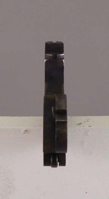
On our project revolver (both revolvers as it turned out) the back strap was sprung and wouldn’t fit back on the frame without a good deal of effort. Since, in addition to putting in the back strap screws we also now have to accommodate the hand spring and plunger, the holes need to line up fairly well or we’ll never get everything back together. Fortunately, the bottom of the back strap is flat and even though there are two thin projections on either side of the hammer slot, they are the same width as the back strap. So, we can set it in a vise with aluminum or some other non-marring material in the jaws and give a little tap with a hammer on the end of a piece of wood. Photo 23.

A couple of light taps and everything lined up perfectly. The next step is purely cosmetic, but made the guns feel much better in the hand.
Photo 24 shows an original 1851 Navy Colt back strap on the left.

The back strap has subtle curves from just behind the hammer slot down to the bottom rear of the back strap. In the middle is the stock Pietta 51 Navy back strap.
There is almost a two inch stretch where the back strap is perfectly flat between the curve behind the hammer slot and before turning out sharply at the bottom rear of the back strap.
The solution was to scribe a line just behind the shoulder stock cut out groove on the bottom of the back strap and then grind up to this line using a belt sander. Then the rear of the back strap was ground on the belt sander to blend in a new curve.
The back strap on the right shows the final contour. Not radically different, but it made the grip feel entirely different. Now that the back strap has been re-contoured, the wooden grip stuck out on the back. The trigger guard, wooden grip, and back strap were screwed to the bare frame and a belt sander used to re-contour the back of the grips and to thin them down. Photo 25.

After the rough contours were cut-in a Black and Decker “Mouse” sander (a small orbital sander) was used to smooth the wood and remove the deep scratches from the back strap. Be careful not to mar the trigger guard as it is fine as is. After the grips were sanded smooth they were removed and paint remover used to remove the rest of the finish.
After the wood was stripped and dried, a few coats of Birchwood Casey Tru-Oil stock finish was applied. No stain was needed, the wood looked great with just the application of the stock finish.
While that was drying the back strap was polished with a small buffing wheel and compound from Sears. Shined up great. Had a few imperfections left over from the belt sanding, but after it’s been shot in a few matches no one will ever notice. Now comes one of the most important steps in our tune-up.
More problems and frustration with cap and ball revolvers arise from misfires, caps falling off nipples, caps that are too tight to seat on the nipples, and cap fragments jamming the gun than all other issues combined. No matter how reliable the mechanicals may be and no matter how smooth the action, all of this is of no consequence if the gun will not fire reliably.
There are always individuals who claim to have perfect performance from stock nipples and any brand of cap they can find at the local firearms emporium. Those circumstances, however, are few and far between. There is only one sure fire way to address ignition and cap problems–the nipples must be consistent in size and the caps must fit properly. The best combination is Treso nipples and Remington #10 caps. No other combination comes close to the reliability of this set-up. Treso nipples are uniform in diameter and have a smooth polished finish. This alone could make the difference between success and failure in shooting your cap and ball revolver.
Another big factor in favor of the Tresos is that the Treso’s flash hole is much smaller than a stock Italian nipple. See, Photo 26.
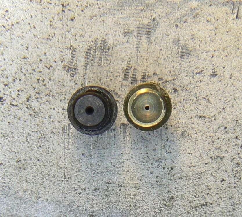
When the gun fires, the ball and most of the gas goes down the barrel. But, gas also blasts rearward out of the nipple flash hole. The larger the flash hole, the more gas escapes and can blow cap fragments off the nipples and into the action.
The only thing keeping the fired cap on the nipple and sealing the escape of gas is the hammer, which is one of the reasons the hammer springs on cap and ball revolvers tend to be fairly heavy.
Bottom line is change the nipples and use the proper caps and most ignition problems will simply go away. The proper size nipples for the Pietta are the 6 x .75mm thread Tresos.
The Treso threads are also cut much more precisely than the stock threads. On the stock nipples they are easily inserted into the cylinder and have a little wobble until they seat.
The Tresos might at first seem to be to big as they can be hard to start and once started have virtually no play as they are screwed into the cylinder. To make sure you can get them back out, coat them with anti-seize compound. Now that the nipples have been installed, we want to make sure they aren’t going to be damaged by the hammer.
Put the hammer into the frame and place the cylinder on the arbor. Line up a nipple with the hammer and lightly push the cylinder back with one hand and push the hammer forward with the other. If you can feel the cylinder move forward, the hammer is contacting the nipple. Remove material from the nose of the hammer until it no longer contacts the nipples. Don’t remove too much material. We don’t want the hammer impacting the nipples, but we don’t want a large gap between the hammer and nipples either.
Now that all the internal parts have been completed it’s time to reassemble the revolver. Put in the hammer and hand, bolt, trigger, trigger/bolt spring and then the trigger guard.
Now depending on how smooth you got all those internal parts you can try the next step. The stock mainsprings on the newer Piettas and Ubertis and much lighter than they were several years ago.
A good piece of advice is to keep the mainspring stiff.
However, this advice is based on using a revolver that has not had our modifications and has stock nipples. IF everything is operating smoothly, and the hammer falls with minimal friction, we can go with a slightly lighter mainspring and still have reliable ignition and avoid cap jams. (Which, again, is why the Treso nipples are so important.)
Use a Wolff mainspring, Brownells part number 969-322-850. It should drop right in, but there is one test to be performed. Slowly cock the hammer and watch the tip of the mainspring. Make sure when the hammer hits the full-cock notch (remember, the back strap is off so don’t pull the hammer back too far) the tip of the spring is not hitting the bottom of the hammer. Photo 27.

If it is, remove a little material from the tip of the mainspring. Install the grips and back strap, put the cylinder on the arbor and install the barrel and wedge. Cycle the revolver several times to make sure everything is operating properly. On our project revolver the cylinder had virtually no side-to-side play, and is now solidly locked up.
If yours has a little play, don’t worry. It is better for there to be a little movement than to have the bolt not dropping fully into the cylinder bolt notches. If everything is operating smoothly grab some powder and balls and get ready to go to the range for some testing. If there is something dragging or not operating correctly, disassemble the gun and using your best detective skills, track down where the problem is occurring and correct it.
At this point another article could be written on the care and feeding of a cap and ball revolver. However, this article has gone long and I will end with just a couple of observations. Colt style revolvers have no cylinder bushing.
This creates two issues:
First, hot gas from the chamber/cylinder gap blows directly on the arbor. Make sure bore butter or some other grease (oil is too thin) is on the arbor or it will quickly foul and cause the cylinder to drag.
Second, again because there is no cylinder bushing, there is nothing to stop the barrel from moving forward when firing except the cylinder physically touching the back of the barrel. Put the revolver on half-cock and pull the cylinder to the rear and hold it up to a bright light. You should see some cylinder gap. Photo 28.

And, since our Pietta has a properly fitted arbor, the gap should be uniform from top to bottom. (Ubertis will typically have a pie shaped gap because of incorrect arbor fit.) Let go of the cylinder and pull the hammer back to the full-cock notch. The gap goes away as the hand pushes the cylinder forward. Photo 29.
When firing, the front of the cylinder gets dirty and it will drag more and more on the back of the barrel as more shots are fired. Use good grease over the balls to help keep the fouling soft and/or wipe the face of the cylinder off every couple of stages.
How did our project revolver(s) hold up on its test run? Fired 50 rounds out of gun one and then brought it home to clean and check everything. The gun was much smoother after firing just 50 rounds and the wedge had loosened just a tad so it could be pushed in just a bit further when the gun was reassembled. (The wedge has not loosened with more shooting.) No misfires, no cap jams. Went back out to the range for a test of the second gun. EMF’s website recommends a charge of between 22 and 28 grains in the Sheriff’s Model. I used a flask with a 25 grain spout. Fired ten rounds with APP. Nice mild load.
Next, emptied the flask and filled it with Goex Cowboy black powder.
Another ten rounds.
More stout than the APP and nothing has that nice satisfying boom of real black powder. Next, ten rounds with 777. Noticeably more stout than APP or Cowboy, but nothing excessive. Finally, while at my local firearms emporium I noticed they had some Pyrodex pellets. These were listed for a .44/.45 cap and ball and were listed as 30 grains equivalent. Ten rounds down range. These clearly had the most power of anything tried. So, test number two; 40 rounds, no cleaning, no misfires, no cap jams. That’s equivalent to eight stages. These were not protracted tests, but the results indicate we have definitely moved in the right direction.
FAQ
How Accurate Were Cap and Ball Revolvers?
Cap and ball revolvers were moderately accurate, sufficient for close to medium-range engagements. The accuracy was influenced by factors like the quality of the ammunition, the shooter’s skill, and the gun’s maintenance.
What Is Cap and Ball Ammo?
Cap and ball ammunition consists of a lead ball, black powder, and a percussion cap. The lead ball is the projectile, black powder acts as the propellant, and the cap ignites the powder to fire the ball.
What Was the Most Popular Cap and Ball Revolver?
The Colt 1851 Navy Revolver was among the most popular cap and ball revolvers. Known for its reliability and balance, it was widely used during the American Civil War and the Wild West era.
What Was the Cap and Ball Weapon?
A cap and ball weapon is a type of firearm that uses a percussion cap to ignite black powder, propelling a lead ball or conical bullet. Notable examples include the Colt 1851 Navy and the 1860 Army revolvers.
Great Information Thanks